Wiring Diagrams – A Complete Guide
Wiring Diagrams are one of the best methods to keep track of how all the components of an electrical system connect. Whether it is a complete building or a small room, the visual representation of components and wires facilitates the understanding of the system and where everything should be.
This article will teach you all you need to know about wiring diagrams, including the many varieties, their applications, the symbols used and how to draw them.
What is a Wiring Diagram?
A wiring diagram is a graphical representation of the actual connections between devices and wires used to better comprehend an electrical system. A home wiring diagram, for example, is a layout of all the light bulbs, plugs, cameras, and so on, relative to the different rooms.
Why Do We Use Wiring Diagrams?
Wiring diagrams are widely used in circuit design and electric applications. The visual presentation improves communication between electrical engineers and technicians who design and install the systems. They also help with safety and regulations checking.
A wiring diagram is also critical for home maintenance and construction projects. A home constructor, for example, can simply determine the appropriate position of light fixtures and electrical outlets to ensure they comply with safety regulations.
What Are The Different Types of Electrical Diagrams?
An electrical wiring diagram is classified into two major types:
1. Schematic Diagram
Schematic diagrams show how a circuit functions logically and electrically. They are used to represent how a circuit works when diagnosing or designing an electrical system, but they do not indicate how the components or wires are physically laid out. Two components can appear next to each other on the schematic diagram yet placed far apart in reality.
2. Wiring Diagrams
A wiring diagram is a simple visual representation of an electrical system’s or circuit’s physical connections and layout. It illustrates how electrical wires are connected and where components are actually connected to the system.
What Are The Main Differences Between Wiring Diagrams & Schematic Diagrams
While Wiring and Schematic Diagrams share many similarities, they can be distinguished by a few essential features.
A wiring diagram illustrates the electrical connections between the various components by using abstract symbols that resemble the object. It shows the physical positioning of each element relating to the others.
A schematic diagram, in contrast, uses lines and normalized symbols to represent the flow of an electrical system. Its main function is to demonstrate the system’s flow, rather than how it is actually laid out.
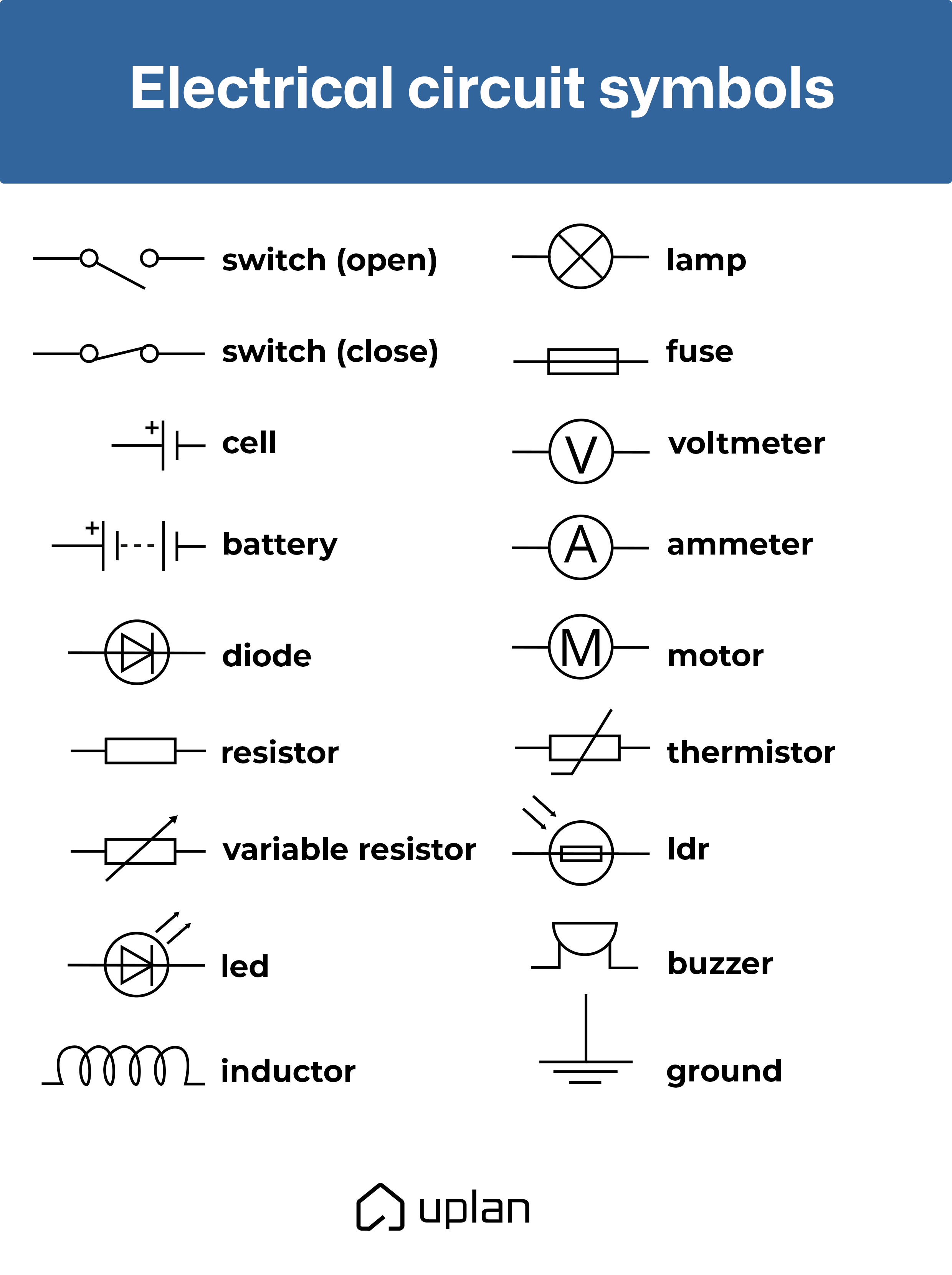
About The Wiring Diagram Symbols
Although the symbols in a wiring diagram are similar to the real object, they can still be difficult to understand. As a result, a basic understanding of the various symbols is required.
A wiring diagram’s symbols include, but are not limited to:
Switches: Switches come in a variety of shapes and sizes. A single-pole/single-throw (SPST) switch has two terminals, with a half-connected line representing the actuator (the part that connects the terminals).
Battery: Batteries, whether cylindrical, alkaline AA’s or rechargeable lithium-polymers, resemble a pair of uneven, parallel lines. More pairs of lines generally indicate more cells in series. The longer line symbolizes the positive terminal, while the shorter line presents the negative terminal.
Resistor: Resistors are depicted on a diagram by zigzagging lines with two terminals extending outward. The international symbol for a resistor, on the other hand, is a featureless rectangle.
Relay: Relays are presented with a coil paired with a switch
Speaker: It takes the form similar to the real life objects they present
Motor: A motor is presented by an encircled M
For more examples, reference the picture below.
Examples of Wiring Diagrams
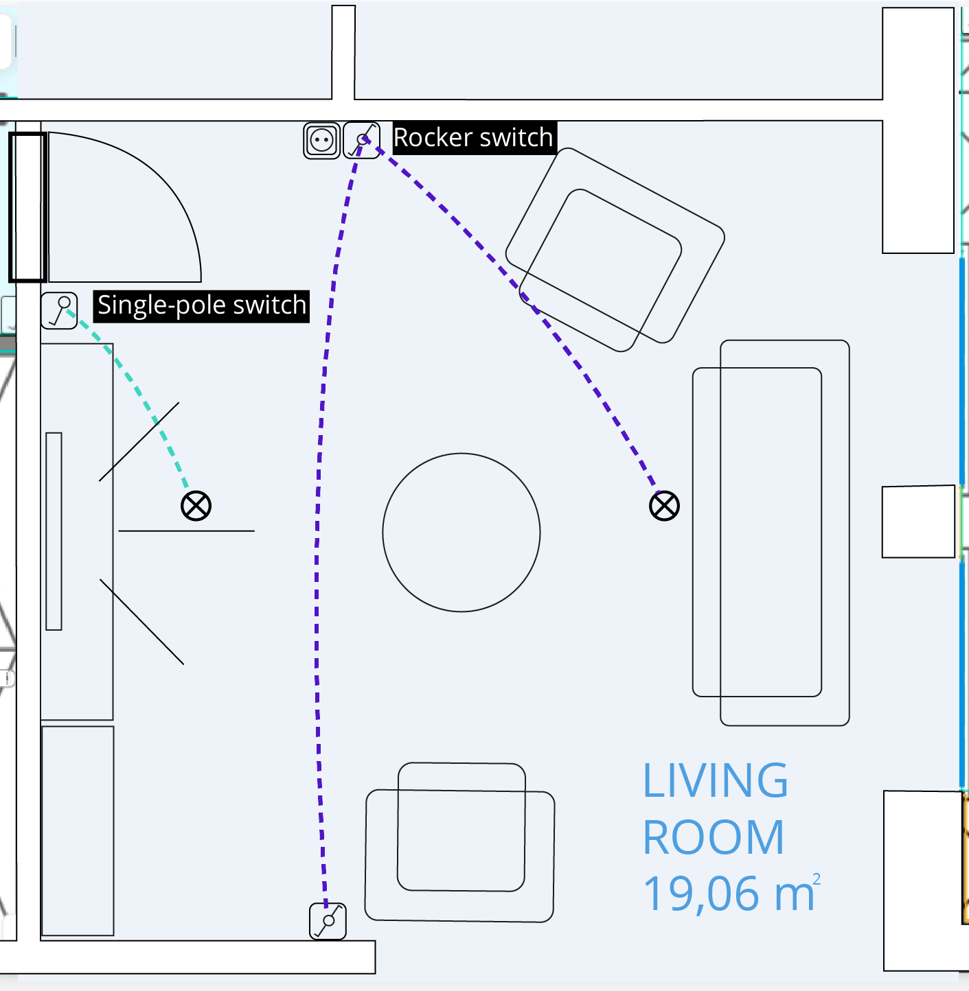
Single-Pole Switch
A Single-Pole switch circuit allows you to control the flow of energy to a load such as a lamp, light, ceiling fan, and so on from a single location. A typical circuit of this type consists of three wires: power, neutral, and ground.
Rocker Switch
A three-way switch circuit is used to operate a light fixture from two places. These are frequently used at the top and bottom of a flight of stairs or at two different entrances to a room.
Socket Outlets
An outlet is a point in an electrical wiring system where current can be taken and used by plugging electrical appliances and equipment into it.
How to draw a wiring diagram
Now that you know what wiring diagrams are and what they consist of, it’s time to start working on your first diagram project. While you can certainly draw the diagram manually, employing tools such as the electrical planning software uplan can make your life much easier.
Here’s an idea of how simple it is to use uplan for your wiring diagram and your complete electrical plan (including a professional offer):
- Step 1. Register for free
- Step 2. Create your project and upload the floor plan
- Step 3. Set the scale and select the rooms
- Step 4. Place the devices (uplan Wizard does that for you in a blink of an eye)
- Step 5. Download the Offer and documentation with Wiring in a single PDF